Product name
-
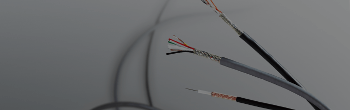
CV、HCV、EM CE/F DC1500V PV-CC Cables for solar power generation systems (PV cables)
-

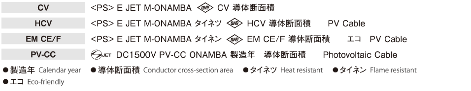
 Product symbols
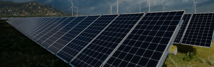
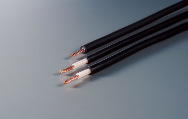
Cables for Solar Power Generation
Product name
Black, white (CV, HCV), black (EM CE/F, PV-CC)
(Line identification is also provided.)
|
No. of cores No. of cores |
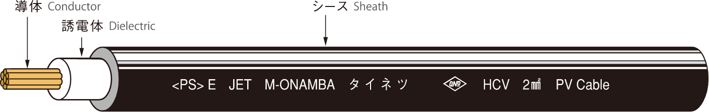
Conductor (AC) Conductor (AC) |
Dielectric Thickness Dielectric thickness mm |
Sheath Thickness Sheath thickness mm |
Finished Outer diameter Finished outer diameter mm |
Conductor resistance Conductor resistance (20°C) Ω/km |
Withstand voltage Withstand voltage (in water) V/minute (in water) V/minute |
Insulation resistance Insulation resistance (20°C) Ω/km |
Reference value Reference value |
|||
|---|---|---|---|---|---|---|---|---|---|---|---|
| Nominal cross- section area Nominal cross-section area mm2 |
Configuration No. of wires / Single wire diameter Configuration No. of wires / Single wire diameter Wires /mm Wires/mm |
Outer diameter Outer diameter mm |
Maximum permissible current (40°C) Maximum permissible current (40°C) A |
Approximate weight Approximate weight kg/km |
|||||||
| CV、HCV | 2 | 7/0.6 | 1.8 | 0.8 | 1.5 | 6.4 | 9.24 | AC 1,500/1 | 2500 | 33 | 60 |
| 3.5 | 7/0.8 | 2.4 | 0.8 | 1.5 | 7.0 | 5.20 | 47 | 80 | |||
| 5.5 | 7/1.0 | 3.0 | 1.0 | 1.5 | 8.0 | 3.33 | 62 | 115 | |||
| EM CE/F | 2 | 7/0.6 | 1.8 | 0.8 | 1.5 | 6.4 | 9.24 | 33 | 55 | ||
| 3.5 | 7/0.8 | 2.4 | 0.8 | 1.5 | 7.0 | 5.20 | 47 | 75 | |||
| 5.5 | 7/1.0 | 3.0 | 1.0 | 1.5 | 8.0 | 3.33 | 62 | 105 | |||
| PV-CC | 2 | 7/0.6 | 1.8 | 0.8 | 1.2 | 5.8 | 9.24 | AC 6,500/5 | 1000 | 33 | 50 |
| 3.5 | 7/0.8 | 2.4 | 0.8 | 1.2 | 6.4 | 5.20 | 47 | 70 | |||
| 5.5 | 7/1.0 | 3.0 | 0.8 | 1.2 | 7.0 | 3.33 | 62 | 95 | |||


Feel free to contact us for more information aboutour company, products, and track record.
Contact Us